Protective Relays are an advanced area of electrical engineering and contracting that can be intimidating, but they don’t have to be! This series of 3 articles will introduce basic relaying to the non-engineers in the solar and energy storage industries.
Intro to Relays #1 – What are Relays, CTs, & PTs? (below on this page)
Intro to Relays #2 – ANSI/IEEE Relay Device Numbers
Intro to Relays #3 – What does SEL stand for?
What is a relay?
The term relay could mean a few different things in the electrical and electronics world, but in the solar industry, “relay” is referring to a “protective relay.”
A protective relay monitors a circuit’s voltage, current, or frequency. When an abnormal condition is encountered, the relay opens or closes a switch to isolate the system.
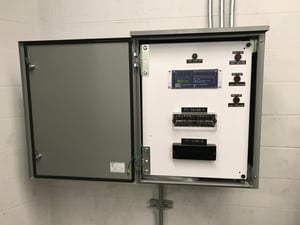
In decades past, relays were electromagnetic devices. Today, modern relays are microprocessor based, which is essentially a computer in a box.
Function
The function of relay is to quickly remove from service any equipment that might suffer damage or otherwise affect the operation of the system.
Relays protect the electrical system in 2 ways:
- Prevent failure or damage to electrical systems.
- Mitigate the effects of failure when it occurs.
A relay monitors the current, voltage, and frequency in a circuit and looks for abnormal operating conditions. When a monitored value goes outside of the specified range, the relay sends a signal to a device (such as a switch) to open or close before the electrical system is affected.
The “electrical system” that relays protect may be the:
- Solar PV or energy storage system
- Building or facility
- Utility’s grid
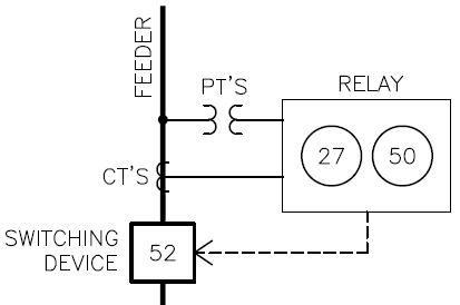
For instance, an overcurrent relay can measure the current on a feeder, and if the current exceeds a programmed setpoint, it sends a signal to trip a circuit breaker and stop the flow of current.
A reverse power relay is an example of an overcurrent relay that protects the utility’s electrical system. If the current backfeeding onto the grid exceeds the utility’s limit, it will shut down the solar system before utility equipment is damaged.
An over-voltage relay is commonly used to protect the inverters and transformers on a utility scale solar PV system. When the relay detects a spike in the voltage, it trips out the system, isolating it from the harmful effects of the high voltage present on the grid.
|
Attention Engineers! Check out our open positions here. |
How is this different than a Circuit Breaker or Fused Switch?
A circuit breaker or fused switch also will interrupt the circuit when current gets too high. However, the functionality is pretty much limited to that. It is only an overcurrent device with limited or no adjustability.
However, a relay can do much more:
- Multi-function: A relay can monitor current and/or voltage, frequency, power factor, etc. In the solar industry, utilities are often concerned about the voltage and frequency on the grid, and if the PV system is producing outside a specified range, it wants your solar system to trip off before it has a negative effect on the grid.
- Custom programmed and flexible – Modern relays use a custom program written by an engineer that determines exactly how it operates. The same model of relay may be used on 10 solar projects, but each one may be programmed differently.
- Separate pieces vs all in one – A circuit breaker is an all in one device. The sensing unit and switch are in the same enclosure. A relay usually consists of several discrete components: a relay, a switch (to open or close the circuit), CTs and/or PTs (more about CTs and PTs below). A relay can be mounted in the same enclosure but isn’t integrated like a circuit breaker.
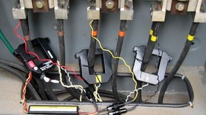
What are CTs?
CTs stands for Current Transformers. They are the devices that measure the current in a circuit. CTs are needed because the circuit’s current is much higher than the relay can handle. CTs step down the current to a low level safe to connect to the relay. When you see a CT with 800:5 ratio, it means it will take a circuit that is operating in the range of 0 to 800 Amps and step it down proportionally to the range 0 to 5 Amps, which is small enough to connect to the relay.
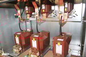
What are PTs?
PTs stands for Potential Transformers. They are devices that measure the voltage and frequency in a circuit. Like CTs, PTs are needed because the voltage in a circuit is much higher than the relay can handle, so they step it down to a much lower level for the relay.
Switching Device
The switching device opens (turns off) or closes (turns on) the circuit. Opening a circuit due to an abnormal condition is commonly referred to as “tripping” the circuit.
In utility scale systems, the switching device is often a recloser or vacuum circuit breaker operating at medium or high voltage. In commercial scale systems, it’s often a 480V or 208V circuit breaker or disconnect switch with a shunt trip option.
Conclusion
At a high level, the concept of relaying is simple. It is a slippery slope that quickly gets more complicated. However, developers and project managers don’t need to know the technical details to do their jobs. That’s why you have experienced engineers such as Pure Power. If you need help with the relays on your project, click here to learn more or reach out to us today info@purepower.com.


.png)