Protective Relays are an advanced area of electrical engineering and contracting that can be intimidating, but they don’t have to be! This series of 3 articles will introduce basic relaying to the non-engineers in the solar and energy storage industries.
Intro to Relays #1 – What are Relays, CTs, & PTs?
Intro to Relays #2 – ANSI/IEEE Relay Device Numbers (below on this page)
Intro to Relays #3 – What does SEL stand for?
Relay Numbers
Protective relays are designed by using standard device numbers to describe its functionality. Instead of verbal descriptions, we use numbers to describe the functions of a relay. The numbers and acronyms are standardized in the document ANSI/IEEE C37.2.
Why use numbers instead of words?
- Efficiency – They are much more efficient to use when creating the wiring diagrams or speaking. For instance, instead of saying “Over Voltage on the Neutral” you can just say “59N”.
- Standardization – When used in conversation, all parties (Utilities, engineers, vendors, installers, etc.) will immediately know what functionality is needed without the risk of misinterpretation and mistakes.
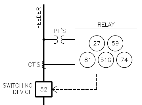
- More compact on a drawing – Since relays provide several functions, it's more concise on a drawing to just call out the numbers. Here is an example of a relay with “phase overvoltage & undervoltage, phase over frequency & under frequency, ground inverse time overcurrent, and alarm” functions. See how much easier it is using the numbers that in you needed to write it all out?
|
Attention Engineers! Check out our open positions here. |
What numbers are used in Solar?
Here are the most commonly used functions in PV and Energy Storage Systems:
|
# |
Name |
Description |
|
25 |
Synchronizing Clock |
Compares the utility and solar circuit’s voltage, frequency, and phase angle. If matching, it allows the solar to connect in parallel to the grid. |
|
27 |
Undervoltage |
Triggers when the voltage is below a set value. |
|
32 |
Directional Power |
Triggers when power flow exceeds a set value in a particular direction. (Reverse Power Relay) |
|
49 |
Transformer Thermal |
Triggers when the temperature of a winding exceeds a set value. |
|
50 |
Instantaneous Overcurrent |
Triggers when current exceeds a defined value. |
|
51 |
Inverse-Time Overcurrent |
Triggers when current exceeds a value for a set amount of time. |
|
52 |
Circuit Breaker |
A device used to open a circuit. 52R means it can also reclose a circuit. |
|
59 |
Overvoltage |
Triggers when voltage exceeds a set value. |
|
74 |
Alarm |
Triggers a visual, audible, or data alarm. |
|
79 |
AC Reclosing |
Controls the reclosing or locking out of an AC circuit interrupter. |
|
81 |
Frequency |
Triggers when frequency is outside the range of acceptable values. |
|
86 |
Lockout |
Locks out operation of a device until manually reset. |
|
87 |
Differential Protective |
Triggers upon a difference between 2 measured currents. |
|
89 |
Line Switch |
A device such as a disconnect switch. Typically, 89 is used only when there are electrical accessories (shunt trip or aux contacts). |
Additionally, there may be letters after the numbers, which further define the function:
|
# |
Name |
Description |
|
R |
Reclosing |
Adding R to a number means it can reclose too. Example: 52R is a circuit breaker that can open and reclose a circuit. |
|
P |
Phase |
Identifies the function is on the phases. Often it's not shown, because it's on phase by default, such as 50 and 51 overcurrent functions. |
|
N |
Neutral |
Adding N means it is on the neutral rather than the phase. Example: 51N monitors the neutral for unbalanced overcurrent. |
|
G |
Ground |
Adding G means it is on the ground rather than the phase. Example: 51G monitors the ground bonding for ground faults. |
Setpoints
It’s not enough to simply call out the functions. Functions also need the minimum and/or maximum setpoint values. These are determined by an engineer and are often unique for each project.
Conclusion
At a high level, the concept of relay device numbers is simple. It is a slippery slope that quickly gets more complicated. However, developers and project managers don’t need to know the technical details to do their jobs. That’s why you have experienced engineers such as Pure Power. If you need help with the relays on your project, click here to learn more or reach out to us today info@purepower.com.


.png)