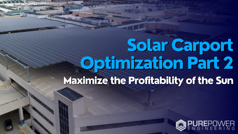
Carports and canopies are the most expensive type of racking or PV module support structure. Therefore, its critical to optimize equipment selection and value engineer these projects.
If you have a hard time getting the costs to pencil out on your commercial solar carport, perhaps some of the concepts in this 2-part series can help.
Part 1: Carports on Ground Level versus On a Building (click here)
Part 2: Equipment Selection and Location Considerations
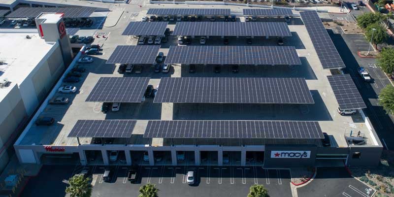
The biggest consideration (and most contentious for some) is where to locate the inverters. You can mount them on the top of the carport columns (image below), or you can mount them at ground level on a separate support structure (such as a strut rack).

Inverter mounted at top of column
Spreading the inverters across columns and structures is a "distributed" configuration. Grouping inverters and mounting them at ground level is referred to as a “virtual central” configuration.
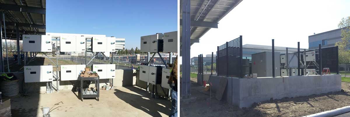 Inverters being installed as a "virtual central"
Usually, Pure Power will recommend keeping the inverters at ground level in a virtual central configuration. (Contrary to almost all the photos others post on LinkedIn). There are a few factors that influence this recommendation for more than half our projects:
Safety and O&M Convenience.
PV carports are usually publicly accessed spaces where energized equipment must be properly guarded. Designers may be tempted to take advantage of these elevated structures and locate inverters high up on the columns. However the inverters are the components most likely to require servicing and replacement over the life of the system so we must also consider the safety of the technicians.
Installers and O&M technicians will need ladders to access inverters located more than six feet above grade. This is not only inconvenient but also introduces fall safety considerations. Locating inverters at ground level mitigates fall hazards and reduces complexity during installation, commissioning, maintenance or troubleshooting.
Communications
When mounting inverters on top of the columns, additional time and material costs are required to run communication circuits to each of the inverters, which are spread across multiple columns and/or carport structures, with long conduit and cable runs up and down columns and in underground duct banks between structures.
When mounting inverters at ground level in a Virtual Central configuration, the string inverters are next to each other so the cost and effort to run monitoring circuits between the inverters is considerably less than distributed string inverters spread throughout the array, reducing CapEX. Additionally, co-locating the inverters improves accessibility for technicians during commissioning, troubleshooting, and routine maintenance, which reduces OpEX.
Free voltage drop for Virtual Central configuration.
Running the DC circuit conductors to the inverter input limits the length of the AC output circuit. More importantly, this design approach shifts the voltage drop from the AC inverter output circuit, where it is most consequential, to the DC side of the system, where it is least consequential. DC voltage drop losses in PV circuits are effectively “free” whenever inverters are “clipping” the output power, as is common around noon on sunny days. As explained in another article, the amount of free voltage drop increases with higher DC-to-AC inverter loading ratios. (click here for more on “free voltage drop”)
Voltage drop percentage.
This distributed inverter placement is sub-optimal when we analyze the percentage of voltage drop within the system. By running more wiring at 1000 or 1500 Vdc and less at 480 or 208Vac you will reduce the voltage drop losses, leading to higher generation over time.
Conductor upsizing.
In order to achieve an equivalent voltage drop, we must up-size conductors more for AC than for DC conductors for the long-distance home runs. Also, to avoid nuisance tripping of the inverter due to AC overvoltage, it is necessary to minimize AC voltage drop in inverter output circuits (but not with DC). In other words, minimizing AC voltage drop in these inverter output circuits is critical to reliable plant operation.
HOWEVER sometimes (depending on the project and design) running many #10 or #8 gauge string wires down the columns and underground to the inverter could cost slightly more than running fewer large gauge AC wires. Using inverters with a single input, with combiner boxes on the columns could alleviate this, but this is a much larger topic that will be covered in a future article.
String Homeruns between Carport structures
A carport is usually sized based on the parking lot area and configuration to minimize the cost of the structure. That is a higher priority than making each canopy an even number of strings or inverters. Inverters with an integral combiner box doesn’t require strings running between structures. Inverters with a combiner box may lead to some strings running underground to a combiner box on another structure, which adds back costs to the project. Once again, each project is unique and the pros and cons need to be weighed.
 Additional Info on the Distributed vs Virtual Central Configurations
A previous article Design Recommendations For 1500-Volt String Inverters. Was intended for ground mounts, but most of the factors also apply to carports. Feel free to read article to see the common and unique design considerations for carports and ground mounts.
Conclusion
As you can see, there are many options for designing a carport system. Each project has a unique set of factors that will influences the weight of the pros and cons of each approach. There is no one-size-fits-all approach to carports. The engineers at Pure Power are experts at evaluating these options, and value engineering a carport project that will reduce your CapEx and OpEx.
For more tips on optimizing commercial- or utility-scale PV power systems, contact Pure Power Engineering to learn more about our value-engineered design and construction drawing services.

.png)