This is a follow up to the article Design Recommendations for 1500V String inverters, where we only briefly mentioned "Free Voltage Drop" and wanted to dive in a little deeper here.
When we value engineer a large solar project, we can take advantage of “free” voltage drop on systems with elevated DC-to-AC ratios. As PV system designs evolve, developers and engineers must constantly rethink best practices for maximizing system efficiency and financial performance. Over the past decade, PV module prices have decreased roughly ten-fold and nominal operating voltages have increased from 600 VDC to 1,500 VDC. As a result of these market and technology changes, typical DC-to-AC inverter loading ratios have steadily increased from a range of 1.15–1.25 to a range of 1.3–1.7.
Introduction to "Free Voltage Drop"
DC Voltage drop is effectively power lost as it travels through the conductors from the array to the inverter input terminals. Generally you want to minimize these losses, because less DC power input to the inverters equals less AC power output by the inverter. The most common way to reduce voltage drop is by increasing the size conductors, under the assumption that spending a little more in CapEx on larger conductors will pay for itself with increased generation revenue over the life of the system. However, that's not always the case.
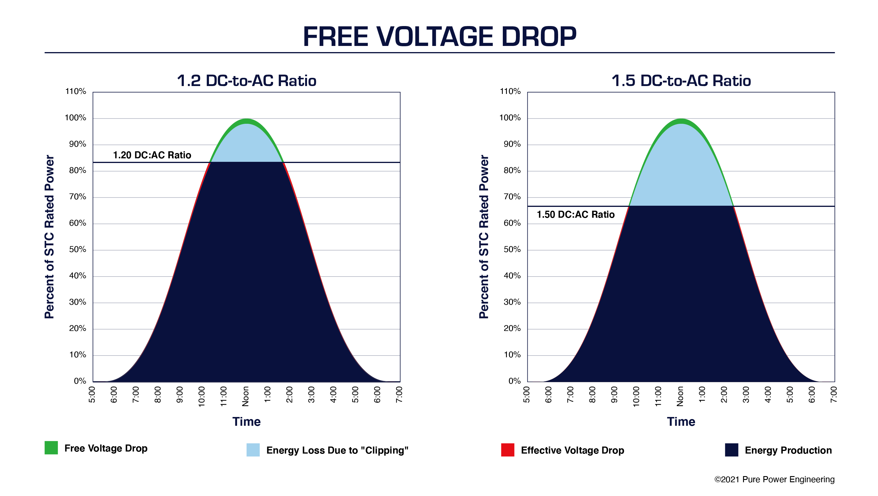
Inverter clipping: When the inverter reaches its maximum AC output it is unable to utilize any more of the DC power from the array. More DC input does not result in any additional AC output. The higher the DC:AC ratio, the more often the inverter output will clip.
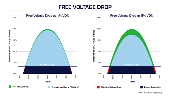
Free Voltage Drop: Once the inverter starts clipping, you have more DC power than you can use so losing some via DC voltage drop losses doesn’t have any effect on the output of the inverter. It no longer costs you generation revenue, therefore its effectively “Free Voltage Drop”. When clipping, it does not matter if the DC conductors are sized for 2% voltage drop or 5% voltage drop—in either case, the system output is the same due to power limiting at the inverter. The upfront investment in up-sizing conductors wont obtain the same ROI as low DC:AC ratio systems with minimal clipping.
Additionally, as the DC:AC ratio increases, the benefit from upsizing conductors to reduce %VD starts to diminish rapidly, so does the amount of free voltage drop which will quickly push out the payback period on up-sized conductors to over 25 years.

Minimize AC Voltage Drop
If the PV source circuits have enough series-connected modules, the string voltage will be adequate to keep the inverter operating in its most efficient MPPT range even if the DC voltage drop percentage exceeds 2%. But having more than 2% voltage drop on the AC circuits can cause nuisance tripping due to high grid voltage. Therefore, limiting voltage drop on the inverter output circuits is more critical than it is on the DC side of the system.
|
Attention Engineers! Check out our open positions here. |
Maximize DC Voltage
The evolution of PV designs to 1,000 and 1,500 VDC also affects voltage drop. Assuming the same system capacity, increasing the nominal operating voltage increases the number of series-connected modules and decreases the number of parallel-connected source circuits. So even if power loss per string remained constant, the system level power losses would decrease because 1,000- or 1,500-volt DC systems have 40% or 60% fewer source circuits than legacy 600-volt systems. In practice, however, increasing the DC system voltage means that the power loss per string does not remain constant but rather decreases significantly. Doubling the system voltage in a DC circuit reduces the I2R conduction losses by one-quarter for the same power level.
Evaluate Voltage Drop Dynamically
The basic equation for calculating the percentage of voltage drop (VD%) in PV power circuits is:

Where L is the one-way circuit length; I is the module operating current; R is the conductor resistance at 75°C; and VSOURCE is the operating voltage of the PV power source. Reviewing this equation, we can clearly see the inverse relationship between VD% and DC source voltage. However, this basic equation provides only a static insight into the VD%. If we assume STC values for voltage and current, we will get one snapshot of the VD%. If we assume PTC values, we will get a different picture of the VD%. In practice, VSOURCE varies dynamically on a daily and annual basis.
In order to determine the effective VD% holistically, we need to account for the fact that this result is a blended average based on a dynamic range of operating conditions. This is possible using PVsyst software or similar to perform an hour-by-hour energy model—also known as an 8760 model—based on typical meteorological year (TMY) data. By using site-specific weather data as a model input, we can account for that fact that hourly irradiance distributions vary from location to location. These differences impact the effective VD% in a PV power system.
All Voltage Drop Is Not Created Equal
When evaluating VD% holistically, it is essential to post-process 8760 model data to account for clipping periods. This analysis has a significant impact on the effective VD% in today’s PV power system design. On paper, static VD% is greatest at periods of peak power. In practice, clipping is coincident with these peak power periods. Moreover, the amount of time that a PV power system is clipping over the course of a year increases at higher DC-to-AC inverter loading ratios. In other words, not only is there a meaningful difference between the maximum theoretical VD% based on a static calculation and the effective VD% based on a dynamic site-specific analysis, but also this discrepancy increases with inverter loading.
In PV power systems with a high DC-to-AC inverter loading ratio, the majority of the theoretical power loss due to voltage drop on the DC side of the system comes at no cost to system performance. Meanwhile, the AC side voltage drop losses do not go away during clipping periods, but rather are most consequential at peak power. That being the case, it is advantageous to locate inverters in these systems near the point of interconnection (POI). Locating inverters near the POI, as I illustrated in a previous blog post, not only minimizes voltage drop on the AC side of the system, but also increases the amount of free voltage drop on the DC side of the system.
For more tips on optimizing commercial- or utility-scale PV power systems, contact Pure Power Engineering to learn more about our value-engineered design and construction drawing services.


.png)