At Pure Power Engineering, our engineers work closely with project originators, developers and EPC firms to reduce the upfront capital costs of construction without sacrificing long-term operating costs. Given the dynamic nature of solar technologies, markets, and evolving codes and standards, we are continuously analyzing and evaluating the impacts of project engineering practices with regards to capital expenditures (CapEx) and operating expenditures (OpEX), as well as energy yield and revenue.
Based on this experience, I provide an overview of the pros and cons of different design approaches to fielding PV power systems with 1,500-volt, 3-phase string inverters. Note that Section 690.7 of the National Electrical Code does not permit 1,500-volt PV system DC circuits “on or in buildings.” As such, these design recommendations apply specifically to commercial and utility ground-mounted applications.
Good: String Inverters Distributed Throughout PV Array
One way to deploy 1,500-volt string inverters in ground-mount applications is to spread out the inverters across the array. In this scenario, the project designer might locate the inverters at a regular interval at the end of a row or array table, ideally along an access road, such that each inverter aggregates PV source circuits from adjacent blocks of modules. Inverter output circuits are aggregated remotely at an AC switchboard ahead of a medium-voltage (MV) transformer.
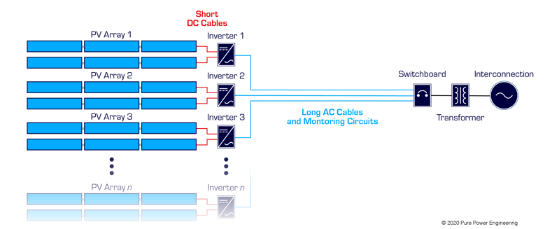
Example layout using distributed string inverters
There is one primary advantage and several disadvantages to a distributed inverter design approach.
PROS
Eliminate combiner boxes. In this scenario, the 1,500-volt string inverter effectively replaces the DC combiner boxes needed in the conventional central inverter architecture.
Multiple Power Point Tracker Some 1500V inverters have MPPT. In this layout you can utilize the multiple PPTs, which could comes in handy if you have tight row spacing and sloping terrain that will cause inter-row shading and mismatch losses.
CONS
Communications. Additional time and material costs are required to make the wired connection to each of the inverters, which are spread throughout the array with long communication conduit and cable runs between each one.
Operations and maintenance. Distributing many inverters across a site inherently increases the time that it takes technicians to commission, maintain, or troubleshoot the system, which negatively impacts OpEX.
Voltage drop percentage. This distributed inverter placement is sub-optimal when we analyze the percentage of voltage drop within the system holistically. Increasing the nominal operating voltage in a circuit proportionally decreases the current, which exponentially decreases voltage drop according to an I2R relationship. In practice, this means voltage drop losses are greater in a 3-phase 480- or 600-volt AC-collection system as compared to a 1,500-volt DC-collection system.
Conductor upsizing. In order to achieve an equivalent voltage drop, we must up-size conductors more for AC than for DC conductors for the long-distance home runs. Also, to avoid nuisance tripping of the inverter due to AC overvoltage, it is necessary to minimize AC voltage drop in inverter output circuits (but not with DC). In other words, minimizing AC voltage drop in these inverter output circuits is critical to reliable plant operation.
|
Attention Engineers! Check out our open positions here. |
Better: Virtual Central Inverter without DC Combiners
The concept behind the "virtual central inverter" architecture is simple. Instead of one big central inverter, multiple string inverters are grouped alongside an AC switchboard and an MV step-up transformer. For example, a “virtual central inverter” consisting of ten 250 kW-rated string inverters could take the place of a single 2.5 MW central inverter.
For a virtual central inverter without DC combiner boxes, PV source circuit conductors land directly in string inverters. This requires that installers bring many small gauge copper PV wires all the way from the PV array to the virtual central inverter.
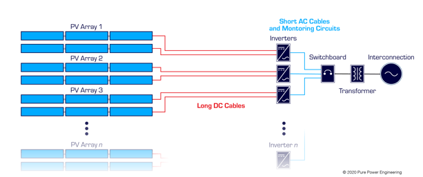
Example layout using long DC cables with a virtual central inverter
There are several advantages and one major disadvantage to a virtual central inverter design without DC combiners.
PROS
Communications. Since the string inverters are next to each other, the cost and effort to run monitoring circuits between the inverters is considerably less than distributed string inverters spread throughtout the array, reducing CapEX.
Operations and maintenance. Co-locating the inverters improves accessibility for technicians during commissioning, troubleshooting and routine maintenance, which reduces OpEX.
Free voltage drop. Running the PV source circuit conductors to the inverter input combiner not only limits the length of the AC output circuit conductors and the percentage of voltage drop. More importantly, this design approach shifts the voltage drop from the AC inverter output circuit, where it is most consequential, to the DC side of the system, where it is least consequential. DC voltage drop losses in PV circuits are effectively “free” whenever inverter power limiting is clipping the output power curve, as is common around noon on sunny days. As I will explain in a future blog post, the amount of free voltage drop increases with higher DC-to-AC inverter loading ratios. (click here for more on free voltage drop)
CONS
Conductor costs. It is expensive to run many small-gauge copper PV source circuit conductors over a long distance from the array tables to the string inverters.
Single Power Point Tracker. On Most 1500V have a single PPT, but for those with multiple MPPTs used on a project with an irregular sloping grade that will create inter-row shading, operating them in single MPPT mode would miss out on the benefit of reduced mismatch losses.
Best: Virtual Central Inverter with DC Combiners
In a virtual central inverter design scenario with DC combiner boxes, PV source circuit conductors terminate within the array at DC combiner boxes distributed throughout the array. As is the case in traditional central inverter-based system design, large-diameter aluminum feeders are used for the DC combiner box output circuit conductors. This design approach requires at least one DC combiner box per inverter.
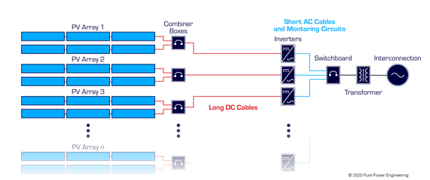
Example layout using combiner boxes with a virtual central inverter
There are several advantages and one major disadvantage to a virtual central inverter design with DC combiners.
PROS
Communications. Configuring string inverters in a virtual central configuration reduces the cost and complexity associated with inverter monitoring and command and control.
Operations and maintenance. Co-locating the inverters improves accessibility for technicians during commissioning, troubleshooting and routine maintenance, which reduces OpEX.
Free voltage drop. System-level conduction losses are minimized because the AC conductor runs are short and DC voltage drop losses are effectively “free” whenever inverter power limiting is clipping the output power curve.
Save with Aluminum Conductors. In a previous blog post, I discuss the cost benefits of replacing copper conductors with aluminum conductors. When we normalize according to the cost for conductor ampacity, aluminum conductors have a significant advantage as compared to copper conductors. In this virtual central inverter design scenario with DC combiner boxes, copper PV wire conductors terminate in close proximity to the PV source circuits. Because we are aggregating multiple source circuits, we can use large-diameter aluminum feeders in lieu of copper PV-type wire for the long distance run back to the virtual central inverter. Best of all, this design approach optimizes CapEX without negatively impacting OpEX or system performance.
CONS
DC combiner costs. On the one hand, this design approach requires DC combiner boxes, which are not required in the previous two scenarios. On the other hand, spending a little money on DC combiners saves a lot of money in terms of conductor costs for the DC collection system. (HOWEVER: In some applications you can avoid the combiner by using wiring systems like Shoals BLA in lieu of a combiner box)
Single Power Point Tracker. On Most 1500V have a single PPT, but for those with multiple MPPTs used on a project with an irregular sloping grade that will create inter-row shading, then you could miss out on the benefit of reduced mismatch losses.
If you are looking for other ways to reduce the capital cost of your commercial- or utility-scale PV power systems, contact Pure Power Engineering to learn more about our value-engineered design and construction drawing services.


.png)