In the first part of this two-part article, I covered the roof membranes and roofing systems commonly used in commercial and industrial (C&I) buildings. Roof identification is important because this information drives other design and engineering considerations in roof-mounted solar applications. While these follow-up considerations are secondary to roof identification, they are nevertheless critically important. After all, these structural, waterproofing and BOS considerations ensure that roof-mounted PV systems do not blow away or inadvertently cause a roof to collapse or leak water.
Structural Considerations
Arguably, the most important part of a C&I roof-mounted solar project is the structural assessment and engineering. Here is a short list of representative lines of inquiry related to the structural assessment and design.
Reserve Capacity Evaluation. The structural elements of existing C&I buildings are usually designed to support the minimum loads required by applicable codes. Exceeding the building’s structural capacity can have catastrophic consequences. Therefore, it’s important to have a structural engineer review and evaluate the envelope of the existing structure to determine whether or not the existing structural elements have the reserve capacity required to support a roof-mounted solar array.
To do so, the structural engineer will review the as-built drawings, where available, or perform a site visit to inspect the existing conditions. This structural evaluation shall consider the additional gravity and lateral loads produced by any new solar equipment and compare these results to the gravity and lateral capacity of the existing building. The engineer must also consider any changes that have occured during the lifespan of the existing structure that were not considered in the original design, such as the installation of new rooftop units or additional layers of roofing over the additional roof.
In some cases, the existing building will have reserve capacity for the rooftop solar system; in other cases, the building will require strategic structural reinforcement to support these additional loads. Therefore, the structural engineer needs to have good experience in this type of evaluation to determine the best and most cost-effective solution.
Mechanical Attachments. While many low-slope C&I roof-mounted solar projects rely on ballast to resist wind uplift, some projects or jurisdictions require mechanical attachments. In a ballasted application, for example, making mechanical connections to the roof structure itself is a good way to reduce dead loads to meet a constrained load-bearing capacity.
A structural engineering plan will not only call out the number and location of attachments, but also detail the hardware requirements. For best results, the mechanical attachment details need to account for the specifics of the roof construction. Some roofing systems include a thick layer of insulation between the roof deck and the roof membrane. To reduce torsional deflection, this insulation may need to be removed and replaced with wood blocking.
Different mechanical attachment methods are used to accommodate different roofing systems. Representative hardware includes U-bolts, OMG Power Grips (pictured below) and S-5! clamps. When using S-5! clamps on a standing seam metal roof, note that the hardware used to connect the roof panels to the roof structure, which is not always easy to inspect and identify, is critical to the structural assessment.
Roof Loading Plan. Once installed, the weight associated with a roof-mounted solar installation is widely and relatively evenly distributed. When the roof is staged for the installation, however, the dead load associated with PV modules, inverters, mounting systems and ballast is highly concentrated.
A roof loading plan ensures that pallets of building materials will be strategically staged over structural elements—such as columns, beams or walls—where the roof is capable of temporarily supporting concentrated loads. In addition to identifying optimal locations for staging equipment on the roof, the roof loading plan will provide guidance regarding the number of pallets or amount of weight that each location can support.
Waterproofing Considerations
While structural attachments are a good way to ensure that roof-mounted equipment resists wind uplift and other environmental loads, each roof penetration provides an opportunity for water ingress. Moreover, roof-mounted solar needs to be deployed in a way that does not damage the roof membrane or prevent roof drainage.
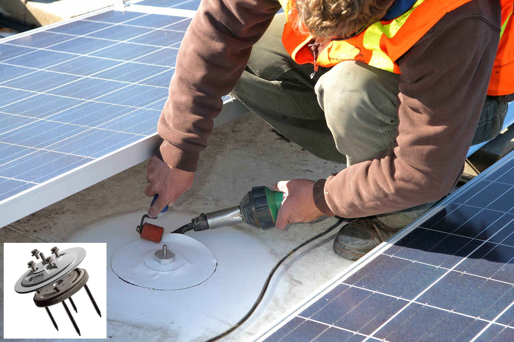
Courtesy OMG Roofing Products
Roof Flashing and Drainage. Flashing is the process of using roof-compatible, waterproof materials to keep water from penetrating a roof system at penetrations, joints, horizontal-to-vertical intersections and so forth. Generally speaking, effective flashing requires coordination between the solar EPC and a qualified roofing professional. Working with a roofer not only ensures material compatibility and proper installation, but may also ensure that any existing roof warranty remains intact.
Low-slope roofs are often incorrectly referred to as “flat” roofs. In order to keep water out of the building, commercial roofs incorporate a variety of roof drainage elements, such as shallow slopes, crickets, drains and scuppers. When retrofitting solar, it is important that the roof-mounted equipment not interfere with the proper operations of these drainage features. Water ponding not only increases roof loading, but also can lead to premature roof degradation. Standing water is also to blame for some types of in-field PV system failures.
Preventing Roof Damage. Single-ply roof membranes are susceptible to physical damage both during and after a solar installation. Repeated foot traffic during installation can damage a membrane, as can an inadvertent drop of a tool. Post-installation, prolonged environmental effects on the mounting system—including wind forces and thermal expansion and contraction—can result in membrane damage.
Installers can mitigate these effects during installation by using temporary protection to reinforce walkways or cushion loading zones. Permanent protection often includes roof-compatible slip sheets or separator pads that act as a sacrificial barrier between the mounting system and the roof membrane. Note that additional walkways may be permanently required to accommodate the new traffic patterns on the roof over the life of the PV system.
If you are looking for more tips to de-risk C&I roof-mounted PV power systems while optimizing performance, contact Pure Power Engineering to learn more about our value-engineered design and construction drawing services.


.png)