Bifacial PV modules convert both front- and back-side irradiance into electricity. This bifacial boost improves solar project performance both in terms of yield and the levelized cost of energy (LCOE). Due to these benefits, bifacial PV modules are increasingly popular in a variety of solar applications including awnings, canopies and ground mounts.
The increased market traction for bifacial PV system designs put even more emphasis on the importance of qualified and specialized engineering supervision. The codes, standards and industry best practices that govern conventional monofacial PV design provide little hard guidance regarding bifacial PV applications. Moreover, different original equipment manufacturers (OEMs)—module companies, racking fabricators and power electronics vendors—often provide conflicting and self-serving guidance.
Navigating these competing interests to arrive at an optimal bifacial PV system design—one that meets applicable codes while maintaining OEM warranties; mitigates performance risk and exposure to liquidated damages; and the optimal balance between energy production and cost—requires an engineering firm with deep expertise and experience working on solar projects in general and bifacial PV systems in particular.
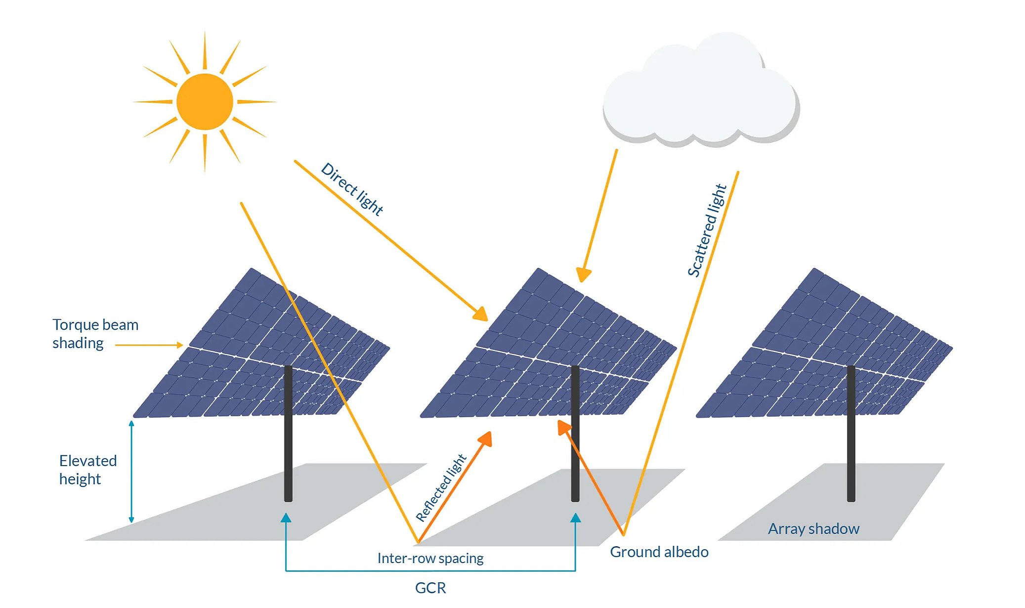
 Courtesy RatedPower
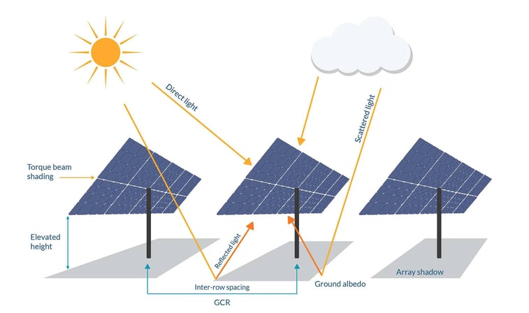
Meeting Code and Maintaining Equipment Warranties
Treating bifacial PV system design as a plug-and-chug activity is a risky proposition. Current in PV power circuits is proportional to irradiance. Since bifacial PV systems collect additional rear-side irradiance relative to a monofacial array, bifacial circuits operate at relatively higher current levels under the same operating conditions due to the back-side contribution. In order to meet code and ensure the practical safeguarding of persons and property, all of the dc circuits in a bifacial PV power system must be engineered to carry these increased currents.
The same is true of the inverters and module-level power electronics used to process dc power within the PV system. The design engineer must ensure that all power conversion equipment operates within a safe voltage and current range published by the manufacturer. Failure to do so may damage the equipment. Even if the equipment is not directly harmed, the out-of-spec operating conditions will void the manufacturer’s warranty.
Voiding the OEM warranty effectively transfers risk from the manufacturer to the EPC or owner. If the product fails due to any out-of-spec operation, the manufacturer has grounds to deny any and all warranty claims. This is true even if you cannot design a system in a reasonable way that stays within the product guidelines, which may be the case with bifacial modules and certain power electronics components.
At present, the National Electrical Code (NEC) does not specifically address bifacial modules in Article 690 or elsewhere. This means that the engineer of record must know how to adapt NEC requirements to bifacial applications. Experience and knowledge are critical to success.
Mitigating Performance Risk and Liquidated Damages
Code-compliant designs always provide a margin of safety when sizing conductors and overcurrent protection devices, which means that the model used to meet the NEC and maintain equipment warranties is inherently conservative. Especially for bifacial PV designs, this model must be based on the site-specific weather data, project-specific equipment configurations, and manufacturer-specific instructions. The hourly results of this detailed model require additional post-processing in order to determine valid design parameters.
If project stakeholders mistakenly apply these conservative design assumptions to the performance model for a bifacial PV power plant, they may effectively overestimate bifacial gains and PV plant production. In order to ensure safe operation, the electrical model for a bifacial PV system must account for worst-case scenarios that may occur over the operating life of a fielded asset, such as elevated irradiance and enhanced albedo in the wake of a winter storm. These conservative design assumptions do not represent typical operating conditions over a full year or account for year-to-year variance in weather patterns.
Since the EPC is on the hook for system performance, a properly implemented performance model will mitigate exposure to the potential liquidated damages associated with underperformance. Mitigating performance risk in bifacial PV systems requires a dedicated performance model, one that accounts for rear-side shading and mismatch; long-term weather trends; average monthly albedo (ground reflectivity); soiling rates (both front- and backside); module degradation and so forth. This highly tuned performance model is critical for the ASTM capacity and performance tests required for project acceptance.
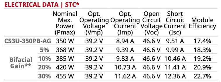 Courtesy Canadian Solar
Maximizing the Ratio Between Energy Production and Cost
Because there are multiple models, value engineering activities are inherently more complex and nuanced in bifacial PV applications as compared to conventional monofacial systems. In monofacial PV applications, the design model and the performance model are generally one and the same. In bifacial applications, there is no one model to rule them all. Bifacial PV systems require two different models, one for project design purposes and another to predict plant performance.
In order to optimize a bifacial project design—whether by improving system performance or reducing system costs—the project engineer must always consider both models holistically. If the project engineer does not consider both models, pulling on one design lever may improve plant performance but sacrifice code compliance. Meanwhile, an overly conservative design approach may leave money on the table.
These considerations are complicated by the fact that different module manufacturers are all over the map in terms of how they characterize bifacial gain in their datasheets. While efforts are underway to standardize bifacial module nameplate ratings, a consensus standard is not yet in place. Some manufacturers provide very detailed bifacial gain specifications. Others provide very minimal information. The onus is on the engineer to understand how best to interpret, interpolate and apply these data points.
Underestimating bifacial gain is a potential safety hazard. At the same time, choosing a 30% gain can kill project finances if that gain is not realized in the field. When project engineers overestimated bifacial gain, they must increase conductor sizes, fuse ratings, arc-fault values and so forth—all of which has a ripple effect on balance of system components. Both of these outcomes are unacceptable.
A design engineer with deep expertise will not only ensure that a bifacial PV system is safe under all possible operating conditions but also that the system is not over designed based on a condition that will never occur at a given location.
Looking for more pro tips for your C&I solar projects? Contact Pure Power Engineering to learn more about our value-engineered design and construction drawing services.

.png)