Pure Power performs many types of power system studies, and the Arc Flash Study may be the most important because it is all about worker safety. However, since it’s not always a code requirement and doesn’t have a direct impact on generation, it is often ignored. We hope this series of articles will inform our clients of the importance of Arc Flash Studies to worker safety.
Part 1: Introduction to Arc Flash Studies (this page)
Part 2: Workplace Safety and Personal Protective Equipment (PPE)
Arc Flash Hazard Analysis studies are prescribed by the National Fire Protection Association—including both NFPA 70E: Standard for Electrical Safety in the Workplace and NFPE 70: National Electrical Code.
What is an Arc Flash Hazard Analysis (AKA Arc Flash Study)?
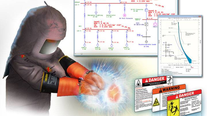
An arc flash event is an explosive and potentially deadly release of energy that accompanies an electrical fault. The basic goal of an Arc Flash Hazard Analysis is to determine the arc incident energy and the arc flash boundary associated with a piece of equipment in the event of a fault.
Since a poorly run Arc Flash Hazard Analysis could put workers in grave danger, it is important that arc flash reports are not dismissed as a “check the box” activity that anyone can do. Only qualified electrical engineers familiar with power studies and the unique characteristics of PV power systems should perform an arc flash hazard risk assessment for solar applications.
Arc Flash Hazard warning labels. Reporting arc flash analysis data on warning labels, as required by the NFPA, ensures that qualified personnel know what level of personal protective equipment (PPE) to wear when inspecting, maintaining, or working on the electrical equipment.
When should you conduct an Arc Flash Study?
An experienced professional engineer can identify opportunities and recommend strategies for reducing incident energy and arc flash hazard category. However, the point at which Pure Power Engineering is engaged ultimately determines how much value we can bring to the project and its stakeholders.
Benefits of early studies. Conducting an arc flash hazard analysis early—as part of a proactive power study conducted during the design stage—provides both short- and long-term benefits. When engaged early in the design process, our team of engineers can identify opportunities to refine construction drawings based on power study results prior to product procurement and construction commencement. For example, we can use the results of a proactive power study to select and specify electrical equipment—such as fast-acting fuses or circuit breakers with an arc-reducing maintenance mode—that streamline commissioning, inspection, and O&M activities over the life of the system by minimizing arc flash hazards.
Challenges of late studies. Assessing arc flash hazards late in the project delivery cycle—such as after product procurement and construction are underway—often results in onerous results that complicate long-term project operations. When engaged late in the delivery process, our team has little opportunity for value engineering and system optimization. Procuring electrical equipment without conducting a comprehensive power study often results in protection coordination issues, increased incident energies, and exposure to avoidable hazards.
Courtesy ETAP
Protection Coordination is a Tradeoff
At a fundamental level, two factors determine arc flash risk and PPE requirements. The first factor is the time that it takes to interrupt the fault. The second factor is the magnitude of the available fault current. Generally speaking, the utility is the 800-pound gorilla in our solar project arc flash hazard analyses. Except when we are analyzing a solar project that incorporates a large energy storage system, the utility is the primary source of dangerous fault currents, especially in today’s high-voltage string inverter-based PV systems.
As a rule, engineers have no control over the utility available fault current and some control over the fault clearing time. All else being equal, reducing fault clearing times is a good strategy for reducing arc flash hazards. In practice, however, there is a tradeoff between protection coordination and arc flash incident energy reduction. For coordination purposes, we want the overcurrent device closest to the fault to be the first one to trip. To accomplish this coordination, we sometimes have to set the upstream overcurrent protection device to wait a certain amount of time to allow the downstream device time to trip. From an arc flash hazard perspective, that time delay can increase the incident energy to which personnel are exposed.
Control Supply-Side Hazards by Design
Supply-side interconnections are common in C&I and utility PV applications. Given that supply-side connections are fed directly by the utility, the magnitude of available fault current is inherently very large. Power transmission and distribution system engineers do not specify overcurrent protection to keep people safe but rather to protect equipment. On the utility side of a supply-side interconnection, it is very rare to have arc flash hazards that are not deadly. Our arc-flash hazard labeling often reflects the severity of the available fault currents by warning personnel to stay out of the equipment, regardless of PPE category. Effectively, the only way to make the equipment safe is to coordinate a utility shutdown.
On the one hand, if there is no need to service the supply-side interconnection equipment, utility shutdown coordination may not prove onerous for asset managers and O&M providers. On the other hand, if project stakeholders need to coordinate a utility shutdown in order to perform repairs—such as fuse replacement—utility coordination could prove challenging over the service life of a system. Under no circumstances should O&M technicians perform live work on the AC side of a PV power system. One way to ensure this level of operational safety is to design systems with the needs of service personnel in mind. Eaton’s double-door safety switch is an example of a product that allows qualified personnel to safely inspect or replace fuses without any exposure to the energized terminals on the utility side of the visible-blade switch.
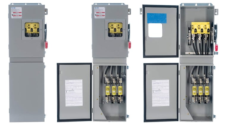
Courtesy Eaton
Look Beyond Worst-Case Labeling
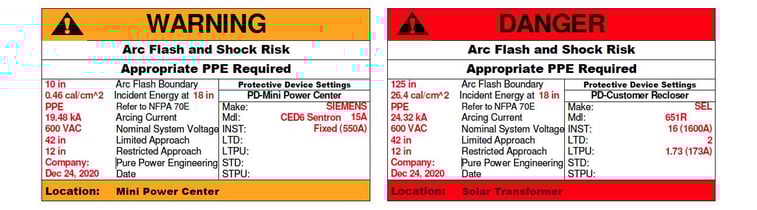
As I will detail in a follow-up blog post, the end result of an arc flash risk assessment is a warning label that is applied to each piece of electrical equipment. This label includes all of the information that a qualified person needs in order to identify safe working practices and select PPE. Generally speaking, engineers report the worst-case exposure information on an arc flash hazard warning label. In some instances—such as inverters and multiple-section switchgear—it may make sense to conduct multiple analyses and install multiple labels.
Inverters. Removing the cover to the input section of a 1,500 VDC string inverter exposes workers to arc flash hazards from both AC and DC terminals, which are presumed live until testing proves otherwise. However, power engineering software tools do not allow users to calculate arc flash hazard for more than one source. Since routine troubleshooting activities often require that workers take current measurements on the DC side of an operating inverter, employers and workers should exercise extra caution given it is not possible to determine the combined arc flash hazard from both sources.
As a rule, Pure Power Engineering will calculate and report the arc flash hazards based on the AC side of the system. Note that this conservative calculation may grossly misrepresent the arc flash hazard that is present after a worker locks out and tags out an upstream AC breaker or switch and verifies the absence of AC power. In string inverter systems, the magnitude of the arc flash hazard on the DC side of the system is quite small. That being the case, modeling the DC arc flash hazard and labeling the inverter with both AC and DC arc flash warning labels may expedite some commissioning and O&M activities over time.
Multiple-section switchgear. Standard practice is for engineers to calculate and label the worst-case arc-flash hazards for switchgear and similar. This hazard is greatest on the supply side of the switchgear, which typically integrates a bolted-pressure switch or a rack-out circuit breaker. Barring a utility shutdown, there may be no safe way for personnel to access any of the utility supply switchgear sections. Adjacent downstream sections of the switchgear often include metering and inverter interconnection breakers. Additional arc flash analysis may be valuable and merited for these distribution sections of the switchgear. By analyzing and labeling individual switchgear sections independently, it may prove possible for personnel with appropriately rated PPE to work safely in the distribution sections, which will provide operational efficiencies over the service life of the system.
Personal Protection Equipment (PPE)
For more on PPE, see our follow up article: Arc Flash Studies for Solar - Workplace Safety
For more tips on optimizing the design of commercial- or utility-scale PV power systems, contact Pure Power Engineering to learn more about our value-engineered design and construction drawing services.


.png)