In a previous article “The 120% Rule Explained – 2011 NEC 705.12(D)(2)” we clarified the philosophy of the 120% rule for load (supply) side interconnections of solar PV systems. The 2011 code was clean, understandable, and easy to safely apply.
In the 2014 National Electric Code, 705.12(D)(2) was expanded to describe how to do a load side tap on feeders & buses. There are now 3 options for interconnecting at a bus bar.
2014 NEC changed for the better, but you may not even realize it since their language is so confusing. Below I will break down the 3 busbar options so you can easily understand when to apply each one.
Option A - 705.12(D)(2)(3)(a) – 100% of Bus Ampacity Rating
The (confusing) code:
The sum of 125% of the inverter(s) output circuit current and the rating of the overcurrent device protecting the busbar shall not exceed the ampacity of the busbar.
The simple equation:![]()
Summary:
Unlike the 2011 NEC where we used the inverter circuit breaker rating, now we use 125% of inverter FLA. This is a small twist that will help us add a few more amps of PV since this will usually be slightly lower because we don’t need to round up to the next size breaker.
This is similar to the 2011 NEC’s 120% rule, except more restrictive because they took away the 120% factor that was applied to the bus rating. If you use this option, there is no restriction on where the backfeed breakers are located.
Option B - 705.12(D)(2)(3)(b) – 120% of Bus Ampacity Rating
The code:
Where two sources, one a utility and the other an inverter, are located at opposite ends of a busbar that contains loads, the sum of 125% of the inverter(s) output circuit current and the rating of the overcurrent device protecting the busbar shall not exceed 120% of the ampacity of the busbar. The busbar shall be sized for the loads connected in accordance with Article 220. A permanent warning label shall be applied to the distribution equipment adjacent to the back fed breaker from the inverter that displays the following or equivalent wording: WARNING: INVERTER OUTPUT CONNECTION; DO NOT RELOCATE THIS OVERCURRENT DEVICE
The simple equation:![]()
Summary:
The left side of the equation is the same as Option A. The difference is the 120% factor applied to the bus bar. This will allow us to connect a larger PV system, and the only restriction is the interconnection must be at the opposite end of the bus as the utility service.
This is almost the same as the NEC 2011, the only difference being 125% of inverter FLA rather than breaker nameplate (which is 125% of inverter FLA but then rounded up).
Option C – 705.12(D)(2)(3)(c) – Sum of inverter and load OCPDs.
The code:
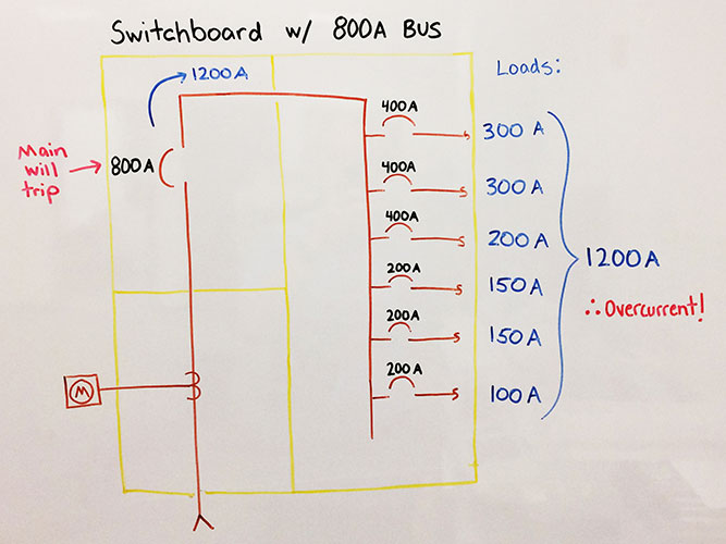
The sum of the ampere ratings of all overcurrent devices on panelboards, both load and supply devices, excluding the rating of the overcurrent device protecting the busbar, shall not exceed the ampacity of the busbar. Permanent warning labels shall be applied to the distribution equipment that displays the following or equivalent wording: WARNING: THIS EQUIPMENT FED BY MULTIPLE SOURCES. TOTAL RATING OF ALL OVERCURRENT DEVICES EXCLUDING MAIN SUPPLY OVERCURRENT DEVICE, SHALL NOT EXCEED AMPACITY OF BUSBAR.
The simple equation:![]() Summary:
Summary:
This usually won’t be used for the interconnection, since including the existing load breakers in the panelboard would likely overload the left side of the equation. However, you can use this for sizing your downstream solar AC collector panels and subpanels, which are often used in today’s string inverter systems.


.png)