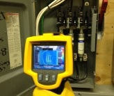
Thermal (IR) cameras are a great tool for preventative maintenance and inspection of your PV system. With a little thermography “know-how” and some image focusing, problems can be discovered quickly before they create a fault or safety hazard in the PV system. Below are issues that can lead to a system fault that the infrared camera can expose:
- Hot spots near lugs from poor wire terminations and untorqued lugs.
- Hot spots on modules- indicating damaged cells.
- Excess heat on feeders created by unbalanced loads
No two sites are alike; therefore, we must calibrate our camera to site specific conditions. Below are two important settings that are often overlooked when using an infrared camera.
Emissivity
Emissivity is how well an object reflects radiation. Very reflective surfaces such as shiny metals have low emissivity. Absorbent surfaces such as rubber and electrical tape have a high emissivity value. Knowing this, the infrared camera will have to be calibrated when measuring bus bars and recalibrated when measuring insulated cable. Unfortunately, frequent recalibration is time consuming but very necessary to obtain accurate measurements. So how do we adjust and maintain two objects with different emissivity properties in one image- like a shiny aluminum mechanical lug and the XHHW jacketed feeder? You could take two different images with respective emissivity settings for each item or you could exploit your knowledge on emissivity and keep both items in one image. I will describe the procedure below, but first, it should be made known that this procedure incorporates contact with mechanical lugs and only qualified persons with de-energizing and system testing training should be performing this procedure:
- Wire insulation has emissivity values of 0.95- equivalent to black electrical tape. Set the infrared camera emissivity level to 0.95 and apply black electrical tape onto the lug. Give the tape a few seconds to adjust to the temperature of the lug. This “surface” will now reflect both the temperature of the lug and also possess the emissivity properties of the wire insulation. Without the tape, the shiny surface would have registered much lower temperatures (due to low emissivity) and presented false results.
- Safety first! Do not apply tape to any exposed components while the system is energized! Even though the system is off, always be mindful of line and load sides!
- Here is a link of various materials and their respective emissivity levels, courtesy of Fluke. http://www.emlab.com/m/store/Fluke%20Thermal%20Camera%20Emissivity%20Values.pdf
If you are using a model by Fluke or Flir, it’s likely the emissivity values are already programmed into the camera and you just have to select the proper one.
Background Temperature
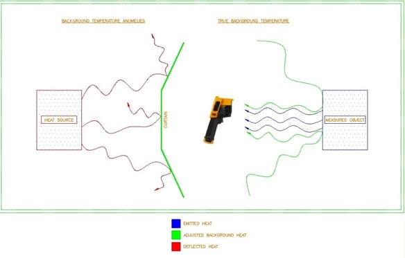
Think of “background temperature” as “reflected temperature.” It is the infrared energy of our surroundings that is being reflected off the object that we are trying to measure. A real world example: Have you ever seen your IR reflection in the image? I tend to see this occur when capturing bus bar images in switchgear or panelboards. It also tends to be more dramatic on colder days when your body heat is much higher relative to the surface temperature of the measured object. This can cause false alarm when looking over the captured image as the alleged “hot spot,” which in actuality is a portion of your reflected body heat, is being registered by the camera lens. Be mindful of this concept. If you see a hot spot on your display, see if simply changing your position will fix this anomaly. If you find yourself in a small or cramped room and hot/cold background objects cannot be avoided from the image, you will have to calibrate your camera and use a curtain. The simplest way is to scan the room and note the average temperature. Adjust for this value in the background temperature settings. Then, place a “curtain” (I use a sheet of cardboard) between the background images and the camera- basically, right behind you. This will prevent any background heat from being reflected off the measured image and reaching the lens.

.png)