
The ac collection system in commercial roof-mounted PV systems generally extends from the inverter ac output terminals to the low-voltage point of interconnection (POI). The exception is when the system interconnects at medium-voltage levels, in which case the ac collection system ends at the low-voltage terminals of the medium-voltage transformer. From a design perspective, the goal of ac circuit aggregation is to field an efficient system that is cost effective; meets building, fire and electrical codes; and satisfies the client. Project stakeholders must locate equipment optimally, route circuits efficiently and size conductors properly.
While ac aggregation on commercial roof-mounted systems can seem challenging—or even aggravating—it is relatively simple if you break it down step-by-step. First, find the shortest path to route circuits from the inverters to the ac combiner, keeping in mind the safety of all those who will have to access the roof after the PV system installation, and then from the ac combiner to the POI. Second, size conductors to meet NEC requirements and limit ac voltage drop. Third, identify the least-costly way to interconnect the system, based on a careful examination of the service switch- board rather than any assumptions about its internal configuration. Lastly, specify equipment that meets all site- and system-specific requirements.
Equipment Placement
The location of inverters and ac combiners in relation to the POI is the starting point for ac circuit aggregation, as equipment placement affects circuit routing.
Inverters and ac combiner. In most cases, inverter placement is relatively inflexible as product selection or Code requirements tend to predetermine inverter grouping and placement. To satisfy the rapid-shutdown requirements in NEC Section 690.12, for example, designers generally need to locate string inverters at or in close proximity to the associated PV source circuits. Microinverter placement is even more limited, as it is fixed by the location of the modules.
Hence, ac combiner location often determines design flexibility with regard to equipment placement. Typically, you should start the design process by locating the ac combiner at the point where the ac circuit will leave the roof and head down to the POI.
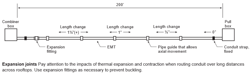
Circuit routing. Most systems use conduit to route and protect ac circuit conductors, with a dedicated conduit feeding each inverter into the ac collection panel. The conductors between the ac combiner and the POI are generally much larger than those for the inverter output circuit; some installations require multiple conduits and paralleled sets of conductors. Unless the project can use an existing conduit between the roof and POI, installers need to add a new conduit run down the outside of the building or through its interior to accommodate these large conductors.
Designers want to identify the shortest possible conduit path across the roof and down to the service equipment. When routing circuits across the roof, however, take care to run conduit in a way that minimizes obstructions to other rooftop equipment such as air handlers. Technicians for other trades must be able to access any serviceable equipment. Also, avoid obstructing access pathways. If this is not possible, you may need to add walkway steps to allow first responders and tradespeople to move freely about the roof.
Conductor Sizing
Though Code-mandated ampacity calculations determine minimum allowable conductor sizes within the ac collection system, designers must also keep ac voltage drop below 1.5% or less to avoid inverter nuisance tripping.
Code requirements. Designers must size conductors in the ac collection system based on the inverter’s continuous output rating [690.8(A)(3)]. Article 310 details the conductor ampacity calculations for general wiring. Electricians and engineers should be familiar with the adjustment factors and ampacity tables that cover ambient temperature, the number of current-carrying conductors per raceway and the conductor installation environment. Depending on the Code edition, conductor height may also impact ampacity calculations.
Table 310.15(B)(3)(c) in NEC 2014 specifies ambient temperature adjustments for raceways or cables based on distance above the roof. In this scenario, it is best to keep the conduit more than 3.5 inches above the roof by using standard rooftop conduit supports. Under NEC 2017, a temperature adder applies only where you install raceways and cables that are exposed to sunlight at a distance of less than 7/8 inch above the roof [310.15(B)(3)(c)].
AC voltage drop. Best practice is to limit the maximum voltage drop within the ac collection system to 1.5% or less to limit the opportunity for ac overvoltage errors. Though some inverter manufacturers recommend designing systems for an ac voltage drop of 1%, realizing this goal can be difficult or expensive in the field. Some designers push ac volt- age drop as high as 2%, but anything higher is worrisome. The risks of operational headaches from nuisance tripping due to errors caused by high grid voltage outweigh any up-front cost savings.
Since troubleshooting ac overvoltage errors in the field is expensive, it is wise to take a conservative approach and keep ac voltage drop within acceptable limits by design. The goal is to specify conductors that are large enough to keep the ac voltage drop below 1.5% without incurring unnecessary costs associated with excessive size. When calculating the ac collection system conductor sizes based on a maximum voltage drop of 1.5%, apply a few restrictions: First, identify the inverter manufacturer’s maximum allowable size for the inverter output circuit conductor, and do not exceed this value. Second, limit the maximum size for the ac combiner output circuit conductor to 500 kcmil copper or 700 kcmil aluminum.
If you cannot limit ac voltage drop to 1.5% based on these parameters, you need to expand your design criteria. If ac voltage drop is greater than 1.5% between all of the inverters and the POI, evaluate voltage drop using paralleled conductors between the ac combiner and the POI; this will reduce voltage drop universally. If only a few inverters see an excessive amount of voltage drop, look for ways to address these specific circuits. For example, adding a splice box outside an inverter can allow for the use of a larger inverter output circuit conductor back to the ac collection panel. However, this also adds labor and material costs.
Optimizing an ac collection system based on voltage drop is an iterative process. If you decide to use paralleled conductors for the ac combiner output circuit, you may need to reevaluate the inverter output circuit conductors. If the voltage drop to some inverters is low, you may be able to reduce output conductor size, provided that you still meet the Code minimum requirements. To the extent that you can identify the right conductor size for each circuit, you can engineer the project for maximum value.
System Interconnection
As detailed in Section 705.12, the Code allows for load-side or supply-side interconnections.
Load side. The rules in 705.12(B) govern interconnections on the load side of the service disconnecting means. Commercial services usually top out at 4,000 A. Depending on the size of the service and the utilization voltage, there may be sufficient backfeed capacity to interconnect a commercial-scale PV system under the 120% allowance [705.12(B)(2)(3)(b)]. In a 1,000 A switchboard with a 1,000 A overcurrent protection device (OCPD), for example, the 120% rule allows you to land 200 A of PV on a 250 A breaker, which would allow for a 166 kWac PV system in a 3-phase 480 V application.
While switchboards all tend to look the same on the outside, they are highly customizable pieces of equipment. You cannot make any assumptions about what is going on under the cover, but must inspect each one individually. How is the distribution bus fed? Though end-fed and center-fed configurations are typical, you may encounter other configurations. Where is the utility section of the switchboard with the service drop conductors and the meter current transducers? Generally speaking, you cannot open this sealed utility section of the switchboard or make an interconnection inside it. Are there any supply-side feeds? I have seen people mistake a supply-side fire pump feed for a main breaker, overlooking the fact that the switchboard did not have a main disconnect. Are there open spots where you can add a PV breaker, or is there an unused breaker for the PV interconnection?
In some cases a switchboard inspection will identify a simple way to make a supply-side connection, which allows for a much larger PV system than a load-side connection does. In addition to capacity limitations, there are other reasons why a load-side connection might not be the best option for a project. It may be difficult and expensive to move a load breaker in order to locate the PV breaker at the opposite end of the busbar from the main OCPD. Meanwhile, interconnections at center-fed or multiple-ampacity busbars incur additional engineering costs. These considerations may favor a supply-side connection.
Supply side. On the face of it, a supply-side connection seems like the easiest way to interconnect a PV system. The Code language on the subject is brief. Though 705.12(A) provides little guidance, it also imposes few restrictions: “The sum of the ratings of all of the overcurrent devices connected to power production sources shall not exceed the rating of the service.” All you need is room on the busbar to land the PV conductors, right? Not so fast—your first goal is to protect the switchboard.
In April 2010, UL’s regulatory services department published an article, “To Tap or Not to Tap?,” providing guidance on this topic. You cannot attach tap conductors to unmarked holes in a busbar. Unless a switchboard has existing holes in the busbar marked “Tap” or the manufacturer’s installation instructions detail how to make a tap, the switchboard is not listed for that purpose. In the absence of a manufacturer- identified field tapping method, AHJs should treat taps as a modification of UL-listed equipment.
The UL paper details a number of potential problems associated with the most common methods of making a supply-side connection. Drilling a hole in a busbar, for instance, reduces its cross-sectional area, which is the basis for its current-carrying capacity. Removing busbar material could lead to elevated operating temperatures or weaken the busbar. Adding lugs at unlisted locations, such as existing holes or terminals, could reduce the air gap required to insulate energized components, increasing the likelihood of an arc flash.
It is up to the AHJ to determine the appropriate recourse when installers modify listed equipment in the field. The AHJ could accept the modification, reject it or require that UL’s field engineering staff evaluate it. While a field evaluation provides the highest level of assurance that the modified equipment will continue to operate safely, it is also costly and time-consuming.
Utility coordination is another potential issue with supply-side connections. To safely connect the PV system, you need the utility to disconnect the power. This is a scheduling issue, especially if the distribution feeder supplies multiple customers or the client has significant restrictions regarding loss of power.
Equipment Specification
The last ac aggregation step is to specify electrical equipment that meets project-specific design criteria. The primary focus is on the ac combiner panel and the PV system ac disconnect.
AC combiner panel. The things requiring attention when specifying the ac combiner panel are the ampacity requirements under normal operation, the available fault current from the POI and the busbar OCPD. In most cases, ac combiner panels are not sized according to the 120% rule but rather based on the sum of the load and supply breaker, excluding the busbar’s OCPD rating [705.12(B)(2)(c)]. Another important—and often over-looked—consideration is the available fault current at the ac combiner in relation to its fault-current rating. This calculation rarely impacts equipment specification in rooftop applications because the length of the conductor between the ac combiner and the POI is generally quite long. If the utility service has a particularly large available fault current, however, and the circuit to the ac combiner is a short one with low voltage drop, take care to avoid specifying a panel and circuit breakers that the process of clearing a fault could damage.
PV disconnect. To specify an ac disconnect for the PV system, select a disconnect with the appropriate voltage and current ratings. However, it is easy to overlook more-complex requirements. If the system interconnects at a circuit breaker on the load side of the service disconnect, for example, many designers specify an unfused ac disconnect. But what about the short-circuit rating? Most unfused disconnects are rated only for 10 kAIC, and the available fault current from the main OCPD could exceed this value.
Most commercial services have an available fault current higher than 10 kA. Since most designs mount the PV system ac disconnect close to the service switchboard, there is little conductor length to lower the fault current value before it gets to the disconnect. To remedy this problem, you can use a fused disconnect with a Class R fuse, or use components that are series rated as a system. In most cases, a Class R fuse provides a higher short-circuit rating than the average commercial service, but you need to verify that the manufacturer’s rating exceeds the fault current available from the utility. To deploy a series-rated system, a Nationally Recognized Testing Laboratory must have evaluated the combination of the disconnect model with the upstream circuit breaker model and, based on the combination, assign a greater AIC rating to the disconnect. Since this setup does not provide the same level of protection as a Class R fuse, cross-check the series rating against the available fault current.

.png)